
 English


Views: 0 Author: Site Editor Publish Time: 2026-09-09 Origin: Site


Solar arrays face a harsh physical reality on every installation site. Even minor environmental obstructions like chimneys, growing trees, or adjacent buildings reduce annual energy production by 5 to 25 percent. In severe cases, a single shaded solar cell drops a string's power output by up to 75 percent, creating a massive bottleneck for the entire system. Standard single-channel string inverters force all connected panels to operate at the current of the weakest, shaded panel. This drastically degrades energy yields and extends the payback period of the photovoltaic system. Modern inverter design offers a structural shift to solve this exact problem. Utilizing an MPPT solar inverter with multiple independent tracking channels isolates these shading impacts. It optimizes energy yield across different roof planes and varying light conditions, providing a highly effective alternative to module-level power electronics.
Shading manifests in three distinct categories across a solar installation, and each requires a specific mitigation approach. Hard environmental shading includes permanent or semi-permanent obstructions. Think of dormers, plumbing vents, parapet walls, mature trees, and adjacent multi-story structures. These cast dense, predictable shadows that move across the array daily in a measurable pattern. Installers can map these shadows during the site survey.
Self-shading occurs primarily in commercial flat-roof or ground-mounted systems. It happens when panel row spacing or tilt angles cause one row of modules to cast shadows onto the row directly behind it during the winter months when the sun angle is low. Soft shading involves the gradual accumulation of environmental debris. This includes pollen, agricultural dust, bird droppings, and snow sliding down the glass. Soft shading diffuses the light before it hits the silicon cells. Each type degrades system performance differently, requiring robust tracking at the inverter level to maintain output.
Solar panels in a traditional string are wired in series to build adequate DC voltage for the inverter to convert into AC power. This series connection creates a distinct physical vulnerability. Electrical current must flow sequentially through every panel in that specific string. You can compare this to water flowing through a single pipe. If you crimp the pipe in one location, the water flow drops for the entire line.
Partial shading restricts this current flow at the exact point of the shaded cells. Because current cannot exceed the capacity of the most restricted point, the entire string is forced to operate at the drastically reduced current level of the shaded module. A single leaf or a narrow shadow from a utility pole can cause a massive output drop for that entire string. The unshaded panels possess the potential to generate full power, but the series wiring bottlenecks their output. This is why string-level isolation is necessary.
Inverters rely on tracking the current-voltage (I-V) curve to find the exact point of peak power generation. Under full sun, a solar string produces a single, smooth curve with one clear peak power point. Shading severely distorts this mathematical curve. Instead of a single peak, shading creates multiple peaks along the curve. These are known as local maxima and global maxima.
Basic inverters often get confused by this distortion. Their tracking algorithms detect a peak, assume it is the highest possible output, and lock onto it. They stop searching the rest of the voltage range. If they lock onto a local maximum instead of the true global maximum, they leave significant usable energy stranded on the roof. Advanced tracking algorithms are required to sweep the entire curve and find the actual highest wattage available.
Bypass diodes are safety components built directly into the junction boxes of individual solar panels. They automatically route electrical current around heavily shaded or damaged cell strings to prevent dangerous localized overheating, known as hot spots. However, bypass diodes are entirely insufficient on their own for yield optimization.
Without dynamic inverter-level adjustment, the system cannot recover the lost power. The inverter will continue trying to pull power at the old voltage level, rendering the bypass diodes ineffective for anything other than fire prevention.
Maximum Power Point Tracking is the core technology driving modern solar efficiency. It involves the continuous algorithmic adjustment of voltage and current to extract maximum wattage from the photovoltaic array. Environmental conditions change constantly throughout the day due to passing clouds, shifting sun angles, and temperature fluctuations. The tracking algorithm reacts instantly to these shifting variables.
Most modern inverters use a Perturb and Observe (P&O) method. The inverter intentionally bumps the voltage up or down by a tiny fraction and measures the resulting current. If the total wattage increases, the inverter continues moving the voltage in that direction. If the wattage decreases, it reverses direction. By constantly calculating the optimal electrical operating point, the inverter ensures the panels are always producing the highest possible yield under the current environmental constraints.
A single MPPT system parallels all connected strings together before applying the tracking algorithm. It essentially averages the voltage across the entire solar array. If you have two strings of ten panels, and one string falls under heavy shade, its optimal voltage drops. Because the strings are paralleled, the inverter averages the two voltages. This pulls the unshaded string off its peak performance point and pushes the shaded string past its optimal point. Both strings underperform.
A multi-MPPT system takes a radically different architectural approach. It physically separates the DC inputs before they are converted to alternating current. This physical separation allows independent voltage regulation for every connected string. The shaded string operates at its own reduced optimal point, while the unshaded string continues operating at absolute peak performance. The two strings never interact on the DC side, completely eliminating the averaging effect.
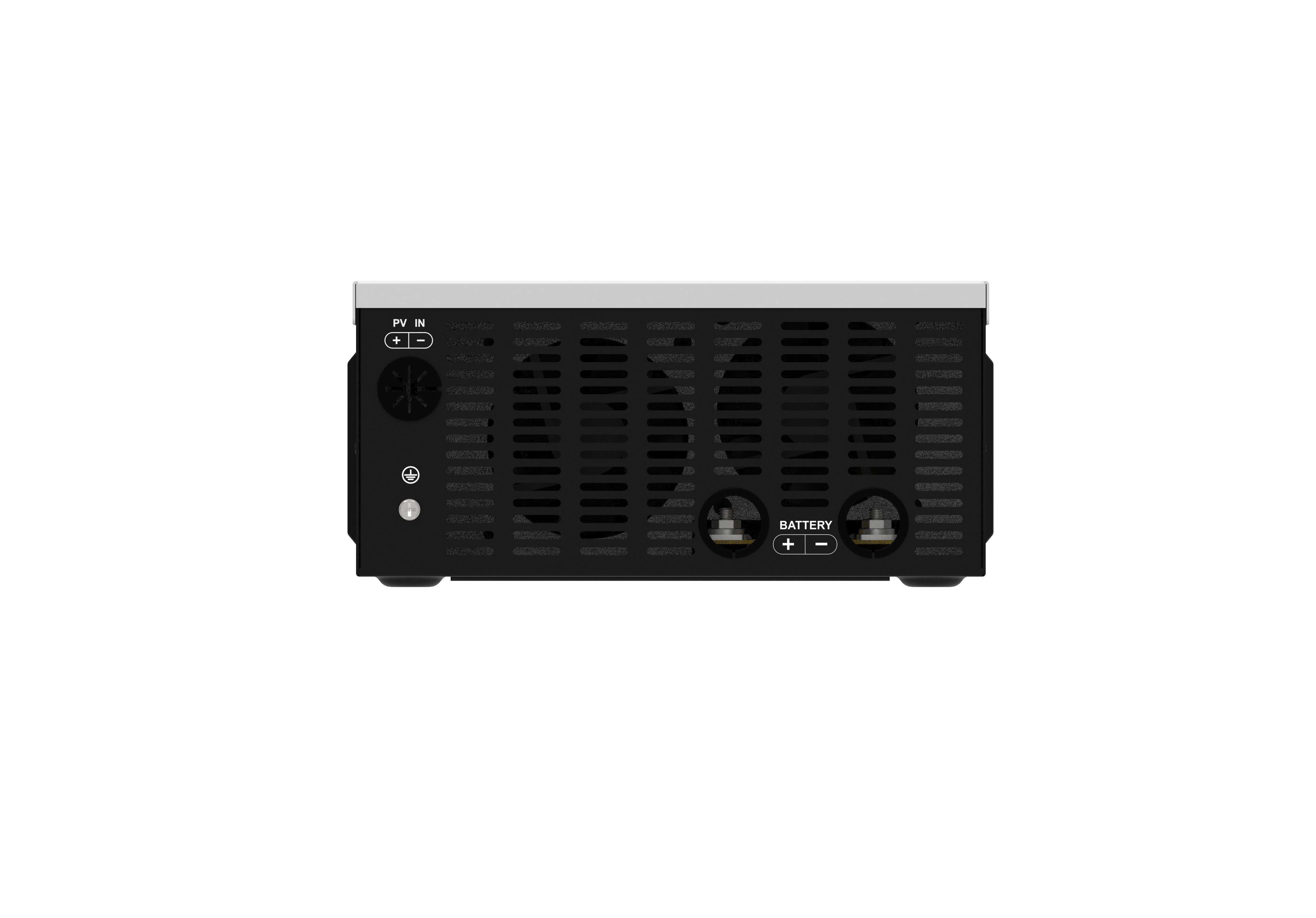
Consider a practical residential installation scenario. A house features a shade-free south-facing roof and a partially shaded west-facing roof. The south roof hits peak production at noon, while the west roof hits peak production at 4 PM. A dual MPPT input inverter handles this complex layout perfectly.
The installer places String A entirely on the south roof and String B on the west roof. The inverter tracks and optimizes both strings completely independently. The morning shade and lower irradiance on the west roof never impact the high-performing south roof. Later in the day, as the sun moves west, the south roof production drops while the west roof ramps up. The inverter adjusts the voltage for each string dynamically. This isolation allows homeowners to utilize secondary roof spaces that would otherwise be deemed unviable for solar generation.
Selecting a wide MPPT voltage inverter is necessary for managing varied environmental conditions and complex string sizing. A wide operating voltage window offers distinct daily advantages on the job site. The inverter starts producing power earlier in the morning when irradiance is low because it has a lower startup voltage threshold. It stays on later into the evening as the sun sets.
More importantly, it maintains stable operation even when bypass diodes drop the string voltage during severe shading events. If a string of ten panels normally operates at 350V, and three panels are shaded, the bypass diodes might drop the string voltage to 245V. Inverters with narrow voltage windows often shut down entirely when the voltage dips below their minimum threshold, resulting in zero power generation. A wide voltage window ensures the inverter stays online and harvests whatever power is left in the unshaded panels.
Microinverters and DC Power Optimizers represent the module-level approach to shade mitigation. They attach directly to every single panel on the roof, providing highly granular optimization. They handle severe, unpredictable shading exceptionally well. However, they compete directly against multi-MPPT string inverters in the residential and commercial markets. String inverters manage shading at the string level rather than the panel level. Understanding the technical differences between these two approaches dictates how you design an efficient and reliable solar array.
Module-level electronics introduce significant upfront hardware costs and require complex roof-level installation. Installers must mount an electronic device under every single panel, increasing labor time and wiring complexity. A multi-MPPT string inverter serves as the superior choice for arrays with moderate, predictable shading. It works perfectly for homes with distinct roof planes but minimal tree coverage.
The threshold for choosing MLPE over a string inverter depends entirely on the site profile. MLPE becomes strictly necessary only for severe, highly fragmented shading where almost every panel experiences different light conditions throughout the day. For standard installations, string inverters provide a much faster return on investment and a simpler installation process.
| System Architecture | Shade Mitigation Level | Ideal Use Case | Hardware Complexity |
|---|---|---|---|
| Single MPPT String Inverter | Array-Level (Poor) | Completely unshaded, single roof plane. | Very Low |
| Dual MPPT String Inverter | String-Level (Excellent) | Moderate shade, two distinct roof orientations. | Low |
| DC Power Optimizers | Panel-Level (Maximum) | Heavy shade, fragmented roof layouts. | High |
| Microinverters | Panel-Level (Maximum) | Severe shade, complex multi-angle roofs. | Very High |
System longevity heavily depends on the total component count exposed to harsh environments. Roofs are brutal operating environments. Temperatures under a solar panel can exceed 150 degrees Fahrenheit in the summer, followed by freezing temperatures in the winter. Electronics degrade faster under extreme thermal cycling. Fewer components on the roof generally translate to lower long-term hardware failure risks.
Centralized multi-MPPT inverters keep sensitive power conversion electronics safely mounted on a shaded wall or in a garage, away from extreme roof temperatures and moisture. This centralized approach simplifies troubleshooting significantly. If a failure occurs, technicians can service the wall-mounted unit immediately. They do not need to set up ladders, climb onto a steep roof, unbolt solar panels, and manage complex wire harnesses just to replace a single failed microinverter.
Determining how many MPPT inputs you require depends directly on your roof orientations and distinct shading zones. You must count your unique roof angles. Two different orientations require at least two independent inputs. If you have panels facing south, east, and west, you need an inverter with three tracking channels.
Complex commercial roofs or large ground mounts might require four or more inputs to properly isolate different sections of the array. Matching the hardware channels to the physical layout is the first step in proper system design. Never parallel strings facing different directions into a single input channel, as this will cause massive voltage mismatch and severe production losses.
Software-based shade mitigation features complement multiple hardware inputs perfectly. Advanced global sweep algorithms periodically scan the full voltage range of the connected strings. Instead of getting stuck on the first power peak they find, they look past local maxima to locate the true global maximum power point.
This software synergy is highly effective during shifting shade conditions. By sweeping the curve every ten to fifteen minutes, the inverter can recover up to 20 to 50 percent of otherwise lost production without requiring any additional rooftop hardware. The sweep takes only milliseconds to complete, meaning the temporary interruption to power generation is negligible compared to the massive gains achieved by finding the correct operating voltage.
Hardware alone does not solve every shading challenge. System owners must employ complementary strategies on the job site. Pairing an MPPT Solar Inverter with bifacial modules can further offset shading losses. Bifacial panels capture albedo light reflected from the roof or ground onto the rear side of the module. This rear-side generation provides a baseline of power even when the front side is partially shaded.
Routine maintenance also plays a critical role in system performance. Performing bi-annual cleaning removes accumulated dust, pollen, and bird droppings. This simple physical maintenance can reduce soft shading and soiling losses to as low as 1.3 percent annually, ensuring the inverter receives the highest possible DC input.
System design requires strict attention to detail to maximize the benefits of multiple tracking channels. Avoid these common design pitfalls during the planning phase.
A: A single MPPT inverter averages the voltage of all connected strings, meaning shade on one string reduces the entire system's output. A dual MPPT inverter separates the inputs physically. It tracks and optimizes two different strings independently, ensuring a shaded array does not impact an unshaded one.
A: When panels are shaded, their bypass diodes activate, which drops the overall string voltage. A wide MPPT voltage window allows the inverter to continue operating at this lower voltage. Narrow voltage windows might cause the inverter to shut down entirely during shading events.
A: No hardware can completely eliminate shading losses because shaded panels physically produce less power. However, an inverter with multiple MPPTs isolates the underperforming panels. This prevents the shading from dragging down the production of the rest of the unshaded solar array.
A: Not usually. For moderate, predictable shading or installations across two or three distinct roof planes, a multi-MPPT string inverter is highly effective. Microinverters are generally only necessary for severe, highly fragmented shading where almost every panel experiences different light conditions.
A: Most standard residential installations require two MPPT inputs. This allows you to split the array across two different roof orientations, such as a south-facing roof and a west-facing roof. More complex roofs with three or more distinct angles may require an inverter with additional inputs.
A: When a bypass diode activates to route current around a shaded cell, the string's total voltage drops. The inverter detects this change. If equipped with global scanning, it sweeps the I-V curve to find the new maximum power point and adjusts its operation to maintain optimal yield.
A: Dirt and debris create soft shading, which restricts current flow and distorts the I-V curve. This forces the MPPT algorithm to operate at lower power levels. Performing routine maintenance, such as bi-annual cleaning, can reduce these soiling losses to as low as 1.3 percent annually.