
 English


Views: 0 Author: Site Editor Publish Time: 2026-09-03 Origin: Site


Managing multiple energy sources simultaneously requires continuous, sub-second decision-making to prevent power disruption and financial inefficiency. Homeowners and facility managers risk wasting generated solar energy, drawing expensive grid power during peak tariff hours, or depleting backup reserves if their system lacks intelligent energy routing. A modern hybrid solar inverter solves this by utilizing programmable algorithms, internal transfer switches, and real-time consumption sensors to automatically route, blend, and prioritize power based on user-defined financial or resilience goals. We see this on job sites constantly. A poorly configured system dumps valuable solar yield back to the utility for pennies. A properly commissioned setup captures that yield, stores it, and deploys it when utility rates spike. The hardware acts as the traffic controller for your electrical panel, ensuring you maximize self-consumption while maintaining a reliable backup reserve.
Most hybrid systems ship with a default operational flow designed to maximize self-consumption and minimize utility draw. The sequence strictly follows a path of Solar to Load, then to Battery, and finally to the Grid. When sunlight hits the panels, the generated direct current (DC) travels to the inverter. The internal components immediately convert the exact amount needed into alternating current (AC) to power active household appliances. If the solar array generates more power than the house is currently consuming, the inverter routes the excess DC power directly into the battery bank via the internal DC bus.
Only when the household load is fully satisfied and the battery reaches its maximum state of charge (SoC) does the inverter allow surplus energy to pass through the utility meter and export to the grid. This hierarchy ensures you utilize every generated watt locally before selling it back to the utility company. Utility companies often credit exported power at a fraction of the retail purchase rate. By prioritizing the load and the battery first, the system prevents you from buying back your own power at a premium after the sun goes down. We always verify this sequence during initial commissioning to ensure parasitic loads do not drain the battery prematurely.
Before any routing decisions occur, the system must extract the maximum possible energy from the solar panels. An integrated MPPT hybrid inverter handles this through Maximum Power Point Tracking. Solar panel output fluctuates constantly based on cloud cover, temperature, and shading. The MPPT algorithm continuously adjusts the electrical load presented to the panels to find the exact voltage and current combination that yields the highest wattage. Modern units often feature dual or triple MPPT inputs, allowing installers to place solar strings on different roof orientations (like east and west) without the shading on one string dragging down the performance of the other.
By embedding this technology directly into the hybrid unit, the system eliminates the need for external charge controllers. This direct integration reduces conversion losses. The internal processor instantly knows exactly how much raw solar power is available for distribution to the home, battery, or grid. Installers configure the string sizing to keep the array voltage within the inverter's optimal MPPT operating window. If the voltage drops too low or spikes too high, the tracking efficiency falls off, reducing the total power available for the routing sequence.
Prioritization requires physical data. The inverter cannot balance loads if it does not know what the house is consuming. Installers place Current Transformers (CT clamps) or dedicated smart meters directly at the main electrical panel, clamping them around the incoming utility lines. In North American split-phase systems, this requires one CT on the L1 leg and another on the L2 leg. These sensors measure the exact amperage flowing into or out of the property in real-time.
They transmit this telemetry back to the inverter via hardwired communication cables, typically using shielded CAT5e or CAT6 wire to prevent electromagnetic interference. If a heavy appliance like an air conditioner turns on, the CT clamp detects the sudden spike in current draw. The inverter receives this signal in milliseconds and instantly throttles up the solar output or initiates battery discharge to cover the new load. Proper installation of these CT clamps is mandatory. If an installer places them backward, the directional arrows point the wrong way, and the inverter will read consumption as export, completely breaking the prioritization logic.
The internal processor acts as the central brain of the entire electrical system. It continuously calculates load demand versus solar generation to make instantaneous routing decisions without any manual intervention. If solar production drops due to a passing cloud, the processor detects the deficit and instantly commands the battery to discharge just enough power to make up the difference. It polls the CT clamps and battery management system multiple times per second using Modbus RTU protocols.
If the battery is depleted, it opens the flow from the grid. This constant, data-driven calculation ensures a seamless power supply. Users never notice lights flickering or appliances stalling because the microprocessor executes these logic gates thousands of times per second. It maintains perfect phase synchronization with the household AC frequency. The processor also logs this data locally and pushes it to a cloud server, allowing users to view historical trends and adjust their priority settings based on actual seasonal consumption habits.
This setting aggressively minimizes grid reliance by prioritizing solar and battery power for all household loads. In Self-Consumption mode, the inverter treats the utility grid as an absolute last resort. During the day, solar runs the house and charges the battery. At night, the inverter discharges the battery to keep the house running. It actively monitors the baseline parasitic loads of the home to ensure no grid power leaks in during normal operation.
It will only draw from the grid if the household demand exceeds the inverter’s maximum output capacity or if the battery reaches its programmed depth-of-discharge (DoD) limit. Installers usually set this DoD limit around 10% or 20% to protect battery health while leaving a small reserve for unexpected outages. This mode is highly effective in regions with flat-rate electricity pricing and low solar export rates, ensuring you consume nearly everything you produce on-site.
Utility companies increasingly utilize Time-of-Use tariffs, charging significantly higher rates during evening peak hours. A hybrid inverter configured for ToU mode actively combats these charges. Users program their specific utility rate schedule into the inverter's interface, accounting for weekend versus weekday rate changes and seasonal shifts.
During expensive peak windows, the inverter locks out grid power and forces the home to run exclusively on battery reserves and any remaining afternoon solar. Once the peak window closes and off-peak rates resume, the inverter switches back to grid power for household loads. It can even use cheap overnight grid electricity to recharge the battery if the next day's solar forecast is poor.
| Time Period | Utility Rate | Inverter Action | Battery Status |
|---|---|---|---|
| Morning (Off-Peak) | Low | Solar powers loads, excess charges battery | Charging |
| Afternoon (Mid-Peak) | Medium | Solar powers loads, excess exports to grid | 100% Full |
| Evening (On-Peak) | High | Battery discharges to power all loads | Discharging |
| Night (Off-Peak) | Low | Grid powers loads, grid charges battery if needed | Charging/Standby |
In areas prone to frequent blackouts or unstable grid infrastructure, financial optimization takes a back seat to energy resilience. Backup Priority mode alters the standard hierarchy by prioritizing the battery above all else. The inverter directs all available solar power to keep the battery at 100% state of charge, maintaining a constant float voltage.
Meanwhile, it uses the grid to power the household loads. If solar is insufficient to keep the battery topped off, the inverter will pull from the grid to charge the battery. This ensures that when a grid failure inevitably occurs, the user has the absolute maximum battery capacity available to survive the outage. We frequently deploy this setting for medical facilities or homes with critical life-support equipment where uptime is non-negotiable. Installers often pair this mode with a dedicated critical loads panel to shed non-essential circuits during the outage.
Many local jurisdictions and utility networks impose strict limits on how much solar power a home can send back to the grid. Some outright ban it to prevent grid voltage instability. In Zero Export mode, the inverter actively prevents excess solar from passing through the utility meter. It requires specific grid profiles loaded during commissioning to comply with local interconnection rules.
It relies heavily on the CT clamps to match solar production exactly to the household load and battery charging requirements. If the house is drawing 2kW, the battery is full, and the panels can produce 5kW, the inverter will intentionally curtail the solar production. It throttles the MPPT down to generate only 2kW. This ensures strict compliance with utility regulations while still maximizing local power usage. If the CT clamps fail or lose communication, the inverter immediately drops production to zero to prevent accidental export.
When the utility grid fails, or for properties entirely disconnected from public infrastructure, the inverter shifts into Off-Grid mode. This involves a physical and software-based disconnect from the utility lines. The internal transfer switch opens, isolating the home. The inverter also manages the neutral-ground bond, ensuring the system remains electrically safe while operating independently from the utility transformer.
The inverter must now balance solar generation and battery reserves exclusively to maintain the microgrid. It establishes the local AC frequency (usually 50Hz or 60Hz) and voltage. If solar production exceeds the load and the battery is full, the inverter alters the AC frequency slightly to signal other AC-coupled components to shut down, or it curtails its own DC intake to prevent system overload. Many units also feature a two-wire dry contact to automatically start a standby gas generator if the battery drops below a critical threshold.
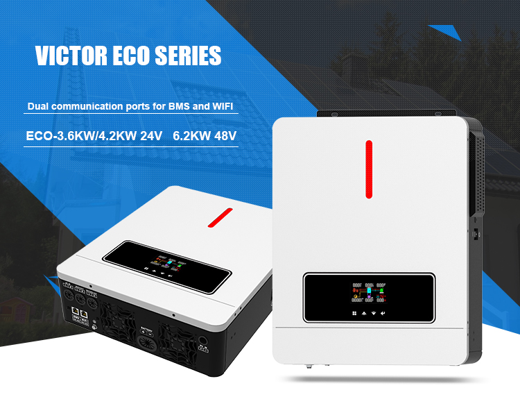
A critical distinction exists between basic backup systems and an advanced grid and battery hybrid inverter. Basic inverters often rely on hard switching; they operate either entirely on battery or entirely on grid power. If a heavy load exceeds the battery's capacity, the system drops the battery and switches the entire house to the grid, causing a momentary flicker.
High-quality hybrid inverters perform seamless power blending using transformerless topologies and fast-switching IGBTs. They synchronize their AC output waveform perfectly with the grid's waveform. If the house suddenly demands 7kW to start a heat pump, but the solar and battery can only safely provide 5kW, the inverter does not shut down. Instead, it holds the 5kW output steady and pulls exactly 2kW from the grid to make up the shortfall. This blending capability drastically reduces utility bills by utilizing every available watt of stored energy without tripping system limits.
Hybrid inverters are inherently bidirectional. They convert DC to AC for household use, but they also convert AC back to DC to charge the battery bank from the grid. This capability is vital during prolonged periods of heavy overcast weather or winter months when solar yield drops. Installers must size the AC input breakers appropriately to handle the maximum charge rate, which can often exceed 50 to 100 amps depending on the battery bank size.
The inverter's logic dictates when this AC charging occurs based on user parameters, such as off-peak tariff windows. Advanced models take this a step further by integrating with local weather APIs via Wi-Fi. If the software detects an incoming severe storm or hurricane, it overrides the standard self-consumption settings and preemptively triggers AC charging from the grid. This ensures the battery is at maximum capacity before the anticipated weather event knocks out the utility power.
Safety regulations mandate strict operational parameters for any equipment connected to public utility lines. When a blackout occurs, a hybrid inverter must immediately cease exporting power. If it continued pushing solar or battery power back through the meter, it would electrify the downed street wires, posing a lethal threat to utility workers attempting repairs.
This safety mechanism is known as anti-islanding. The inverter continuously monitors grid voltage and frequency. The moment it detects a grid failure, internal contactors physically break the connection to the utility in under 20 milliseconds. The inverter then shifts into island mode, routing power only to the home's critical loads panel while keeping the external grid connection completely dead. Compliance with standards like UL 1741 SA/SB or IEEE 1547 ensures these disconnects happen reliably every single time. The system also integrates with rapid shutdown devices (NEC 690.12) to kill panel voltage during a fire emergency.
The most common failure point in hybrid system design is undersizing the inverter's continuous AC output rating. An inverter might be paired with a massive battery bank and a large solar array, but if the inverter itself is only rated for 5kW of continuous output, it cannot power a 7kW household load during a grid outage.
When grid power is present, the inverter simply blends utility power to cover the deficit. However, in off-grid or backup mode, exceeding the inverter's capacity will cause the system to trip on overload protection, shutting down the entire house. Installers must carefully calculate the home's peak simultaneous load and account for the Locked Rotor Amps (LRA)—the massive momentary surge required to start heavy motors like well pumps or air compressors—when selecting the inverter size. Installing soft starters on heavy motor loads often prevents these nuisance trips and protects the inverter's internal components.
How an inverter connects to the battery bank heavily influences system efficiency. A true hybrid inverter utilizes DC coupling. This architecture provides superior round-trip efficiency for new installations.
In contrast, AC-coupled systems require solar DC to be converted to AC by a standard inverter, then converted back to DC by a separate battery inverter for storage, and finally back to AC for use. Each conversion step loses 3% to 5% of the energy as heat. DC-coupled hybrid inverters eliminate these redundant steps, preserving more generated power for actual household consumption and reducing the amount of hardware mounted on the wall.
The inverter cannot safely prioritize battery charging or discharging without seamless communication with the Battery Management System (BMS). Modern lithium iron phosphate (LiFePO4) batteries have strict parameters regarding maximum charge current, discharge rates, and temperature thresholds. Operating outside these parameters voids warranties and risks catastrophic failure.
The hybrid inverter connects to the battery bank via CAN bus or RS485 communication cables, establishing a closed-loop system. The BMS constantly dictates its limits to the inverter. If the battery is cold, the BMS will instruct the inverter to throttle back the charging current to prevent lithium plating. If the inverter loses this communication link, it defaults to a safe, highly restricted open-loop operational mode or shuts down battery usage entirely to prevent hardware degradation or thermal runaway.
Hardware capabilities mean little without robust software to govern them. The manufacturer's firmware dictates how quickly and accurately the inverter responds to load changes and grid fluctuations. Frequent firmware updates are necessary to maintain compatibility with evolving grid regulations and new battery chemistries.
Effective energy prioritization requires an intuitive user interface. Homeowners need clear, real-time dashboards showing solar generation, battery SoC, household consumption, and grid import/export. Without reliable monitoring software, users cannot verify if their Time-of-Use schedules are functioning correctly or if their zero-export limits are successfully preventing utility penalties. Installers rely on these same portals for remote troubleshooting, allowing them to adjust priority parameters, update grid profiles, and diagnose faults without rolling a truck to the site.
A: Installers place Current Transformers (CT clamps) or smart meters at the main electrical panel. These sensors measure the exact current being drawn by the house and send this real-time data back to the inverter's processor via hardwired communication cables, allowing it to adjust output instantly.
A: Yes, many hybrid models function initially as standard grid-tied inverters. They route solar power to the house and export excess to the grid. This allows users to install the solar array first and add battery storage later without replacing the inverter.
A: It can, but this is a programmable setting. Users typically reserve grid charging for off-peak tariff periods when electricity is cheap, or they use weather-integrated software to preemptively charge the battery from the grid before an anticipated storm causes an outage.
A: Once the household load is met and the battery reaches 100% capacity, the inverter exports the excess energy to the utility grid. You receive credits for this power, assuming net metering is active and you have not enabled zero-export limits.
A: Yes, by selecting Backup Priority mode. In this setting, the inverter routes all solar generation directly to the battery first. It uses grid power to run the household loads until the battery is completely full, ensuring maximum readiness for a blackout.
A: Advanced hybrid inverters detect grid failure and physically disconnect from the utility in 10 to 20 milliseconds. This transfer time is fast enough to function as an Uninterruptible Power Supply (UPS) for most standard appliances, keeping lights on and computers running without resetting.
A: No. The MPPT charge controller is built directly into the hybrid inverter's circuitry. This integration simplifies the physical installation, reduces equipment costs, and improves energy routing efficiency by minimizing unnecessary DC-to-DC conversion steps.