
 English


Views: 0 Author: Site Editor Publish Time: 2026-09-05 Origin: Site


Standard grid-tied solar systems share a major vulnerability. When the utility grid fails, the solar power shuts down completely. This intentional shutdown prevents backfeeding electricity into dead power lines, protecting utility workers. However, it leaves your facility entirely without power during an outage. Mode-switching technology resolves this limitation by providing continuous power through grid interruptions.
Managing power continuity presents a strict technical challenge. Transitioning between grid-synchronized power and independent battery power requires precise voltage matching and exact phase synchronization. Rapid physical switching is mandatory to prevent equipment damage and ensure electrical safety. An inverter must execute these steps flawlessly within milliseconds.
This technical breakdown examines how these transitions occur. We analyze the hardware components that dictate switching speed and show you how to evaluate transfer specifications. You will learn to select the right equipment for resilient, continuous energy systems.
An On Off Grid Solar Inverter operates across distinct modes to manage energy flow. Each mode requires specific internal logic and hardware configurations. The system continuously monitors external conditions to determine the appropriate operating state.
In grid-tied mode, the inverter operates in parallel with the utility grid. It acts as a current source. The inverter must perfectly match the grid voltage and frequency. It achieves this using a Phase-Locked Loop (PLL) circuit. The PLL continuously monitors the grid waveform zero-crossings. It adjusts the internal oscillator to align the injected current exactly with the grid voltage phase.
The power flow logic prioritizes local consumption. The system routes solar energy directly to the active electrical loads. We use Current Transformers (CTs) clamped around the main incoming utility lines to measure house consumption. If solar production exceeds load demand, the inverter charges the battery bank. Once the batteries reach full capacity, the inverter exports the remaining excess DC-to-AC converted power to the utility grid. This export process often generates net metering credits.
In jurisdictions without net metering, we configure the inverter for zero-export. The CTs monitor the main lines, and the inverter dynamically throttles solar production to match exact house consumption, ensuring zero watts bleed back to the utility.
Modern inverters utilize programmable logic and Time-of-Use (TOU) algorithms. Software dictates power priorities based on utility rate schedules. During peak rate hours, the system executes peak shifting. It discharges battery power to support local loads. This reduces reliance on expensive grid electricity. During off-peak hours, the system maximizes self-consumption or charges batteries from cheap grid power. The inverter shifts dynamically between grid and battery power without requiring a grid outage.
When the grid fails, the inverter enters off-grid mode. It stops operating as a current source and becomes a voltage source. It must establish and maintain the local micro-grid voltage and frequency independently.
There is a distinct difference between active islanding and a standby state. Active islanding involves the inverter forming a local micro-grid. It continuously powers a dedicated backup panel. A standby state means the inverter shuts down its AC output entirely. It remains dormant, keeping batteries charged via solar, until the utility grid returns.
To establish the micro-grid, the inverter relies on an internal reference oscillator. It uses Pulse Width Modulation (PWM) to synthesize a clean 60Hz or 50Hz sine wave. The internal processing circuitry generates this waveform without any external grid reference. The voltage regulation must remain tight to prevent flickering lights or equipment faults.
Off-grid operation relies entirely on local energy reserves. The inverter balances load demands dynamically using solar PV input and battery discharge. If a heavy load turns on, the inverter immediately pulls more current from the batteries. The system must manage these sudden load spikes without the infinite inertia of the utility grid to stabilize the voltage.
Bypass mode provides a failsafe mechanism. It ensures uninterrupted power to the loads if the inverter hardware fails. Bypass systems utilize internal solid-state switches or external manual rotary switches.
Internal bypass switches activate automatically during specific fault conditions. If the inverter experiences a severe internal fault, a sustained overload, or a thermal shutdown, the internal logic triggers the bypass. The system routes the incoming grid AC power directly to the output load terminals. This completely bypasses the inverter processing circuitry, transformers, and power stages.
External bypass switches allow for manual maintenance. Technicians can physically switch the power flow to bypass the inverter entirely. This permits safe isolation, power cycling, or complete hardware replacement. The facility maintains continuous grid power while the solar equipment remains safely de-energized.
| Operating Mode | Inverter Function | Grid Interaction | Primary Power Priority |
|---|---|---|---|
| Grid-Tied (Interactive) | Current Source | Synchronized / Exporting | Local Loads > Battery > Grid |
| Off-Grid (Island) | Voltage Source | Physically Disconnected | Local Loads > Battery |
| Bypass (Failsafe) | Inactive / Passthrough | Direct Connection to Loads | Grid Power Only |
Understanding how a hybrid grid solar inverter manages transitions reveals the complexity of modern power electronics. The switching process involves rapid detection, physical disconnection, and precise synchronization.
The switching sequence begins with grid loss detection. The inverter continuously monitors the grid connection for anomalies. Technical triggers include severe voltage sags, rapid frequency shifts, or a complete loss of the grid AC signal. Advanced detection algorithms use Rate of Change of Frequency (ROCOF) and vector shift measurements to identify grid instability instantly. We see this in the field when local transformers blow; the inverter detects the voltage drop before the lights even flicker.
Anti-islanding is a strict regulatory requirement. Standards like UL 1741 and IEEE 1547 mandate this safety feature. When the inverter detects a grid failure, it must disconnect within fractions of a second. This prevents the inverter from backfeeding power into a dead grid. Backfeeding poses a lethal electrocution risk to utility lineworkers repairing the downed lines.
The physical disconnection relies on a transfer relay or contactor. This component physically breaks the electrical connection between the inverter output and the utility grid. High-quality systems use robust electromechanical contactors paired with solid-state components for arc suppression.
Internal transfer switches reside directly on the inverter circuit board. They manage the transition for dedicated sub-panels. These internal relays typically handle 40A to 60A of pass-through current. External Automatic Transfer Switches (ATS) handle much larger loads. An ATS sits between the main utility meter and the main electrical panel. It physically disconnects the entire facility from the grid, allowing the inverter to power the whole home safely.
Returning to grid power requires careful execution. The inverter cannot blindly close the transfer relay when grid voltage returns. An out-of-phase reconnection would cause massive transient currents, potentially destroying the inverter and damaging home appliances.
The system initiates a strict wait and verify period. Regulatory standards typically require a 1-minute to 5-minute observation window. The inverter monitors the grid to ensure the voltage and frequency remain stable. This prevents the system from reconnecting during intermittent grid sputtering.
Once the grid proves stable, the inverter begins phase synchronization. The internal oscillator makes micro-adjustments to its generated sine wave. It slowly speeds up or slows down its frequency. It aligns its waveform peaks and zero-crossings perfectly with the grid waveform. Only when the phases lock completely does the logic controller send the signal to close the contactor.
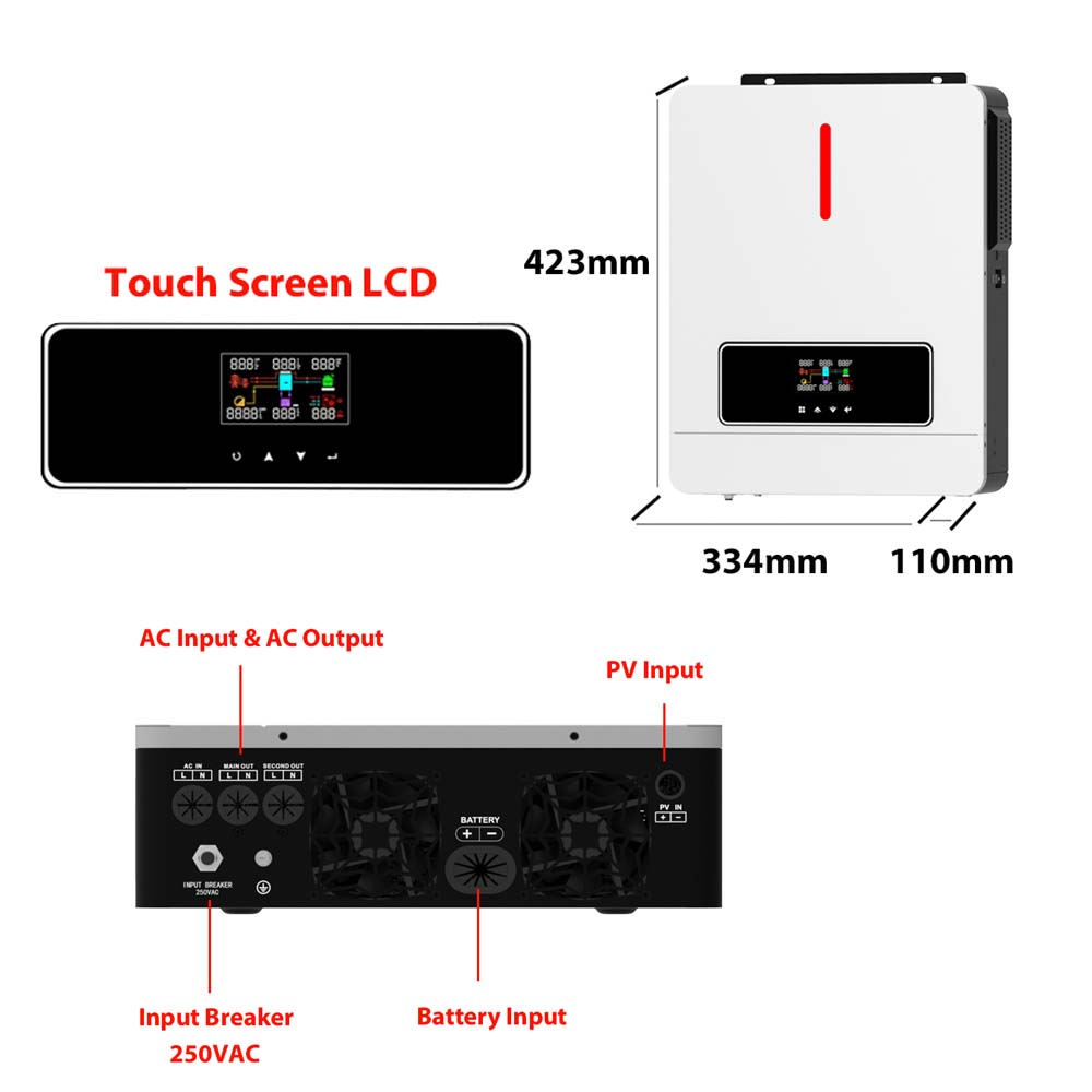
When selecting a backup load solar inverter, transfer time metrics dictate system capability. The speed of the transition determines what types of equipment will survive the outage without disruption.
Transfer time measures the delay between grid loss and the restoration of battery-supplied AC power. A standard 60Hz AC waveform completes one full cycle every 16.6 milliseconds. Industry standards divide transfer times into two main categories.
Uninterruptible Power Supply (UPS) grade inverters achieve transfer times under 10 milliseconds. This transition occurs in less than one half-cycle of the AC waveform. Standard Emergency Power Supply (EPS) inverters typically feature transfer times of 20 milliseconds or higher. This slower transition spans more than a full AC cycle.
A 20ms gap in power creates significant operational issues for sensitive electronics. Most computer power supplies contain internal capacitors designed to hold a charge for about 15 to 20 milliseconds. If the transfer time exceeds this hold-up time, the voltage drops to zero.
Desktop computers will hard reboot. Servers will drop active connections and potentially corrupt data. Medical equipment may trigger fault codes and require manual resets. Smart home automation hubs may lose connection to the network. Evaluating an inverter requires matching the transfer time to the specific sensitivity of the intended backup loads. If you run a home office or critical servers, a sub-10ms transfer time is mandatory.
Switching modes presents a severe challenge when heavy motor loads are running. HVAC compressors, well pumps, and large power tools require massive inrush currents to start. This is known as Locked Rotor Amps (LRA). The LRA can be five to seven times higher than the Running Load Amps (RLA).
When the grid drops, the inverter must instantly supply this surge current to keep the motor spinning. If the motor stalls during the transition, it will demand its full LRA from the inverter. You must evaluate the continuous output rating versus the peak surge rating in off-grid mode. An inverter might provide 5kW continuously but need a 10kW surge rating for 5 seconds to successfully transition a running well pump.
We often install soft starters on HVAC units to reduce this inrush demand. A soft starter ramps up the voltage gradually, cutting the LRA by up to 60%. This modification protects the inverter components and prevents the battery BMS from triggering an overcurrent shutdown during the transition.
| Equipment Type | Tolerance to Power Gap | Recommended Transfer Time | Potential Failure Mode |
|---|---|---|---|
| Desktop Computers / Servers | Low (15ms hold-up) | < 10ms (UPS Grade) | Hard reboot, data corruption |
| Medical Devices (CPAP, Monitors) | Low | < 10ms (UPS Grade) | Fault codes, shutdown |
| LED Lighting | Medium | < 20ms (EPS Grade) | Visible flicker |
| HVAC / Well Pumps | High | < 50ms | Motor stall, high inrush demand |
Even with advanced automation, an on off grid inverter requires manual override capabilities. Understanding both protocols ensures safe operation and proper maintenance procedures.
Modern hybrid systems handle transitions entirely through the onboard logic controller. The automated process requires zero human intervention. The voltage sensors detect the outage. The logic board triggers the transfer relay. The DSP (Digital Signal Processor) shifts the power stage from current-source to voltage-source mode. The battery management system ramps up discharge current. This entire sequence executes in milliseconds, providing continuous power to the end user.
Manual switching remains a mandatory feature for system maintenance. Technicians must perform firmware updates, troubleshoot wiring faults, or replace degraded components. Manual disconnects allow personnel to de-energize the inverter without dropping power to the facility's main electrical panel.
Executing a safe manual power cycle requires a strict step-by-step procedure. Incorrect sequencing causes dangerous DC arc flashes and damages internal capacitors. Follow this standard sequence:
Improper system design neutralizes the benefits of fast transfer times. Implementing a hybrid system requires strict adherence to electrical codes and component matching.
Architectural trade-offs define the installation process. Routing all facility loads through an inverter's internal transfer switch is usually unfeasible. Most internal relays have strict pass-through amperage limits, typically capped at 50A or 60A. A standard residential main panel operates at 200A.
Attempting to pass 200A through a 50A relay will melt the contactor and destroy the inverter. Therefore, installing a dedicated critical load sub-panel is necessary. Electricians move essential circuits from the main panel to this sub-panel. The inverter powers only the sub-panel. This architecture prevents system overloads during an outage and ensures the inverter remains within its thermal limits.
When the inverter disconnects from the grid, it must often establish a new neutral-to-ground bond to satisfy electrical codes and ensure breakers trip during a fault. High-end inverters include an internal N-G bonding relay that automatically closes when the grid drops and opens when grid power returns. Failing to account for this during installation leads to floating neutrals, which causes erratic voltage fluctuations and damages sensitive appliances.
Battery bottlenecking is a primary implementation risk. The inverter can only supply as much surge power in off-grid mode as the battery bank allows. Every lithium battery contains a Battery Management System (BMS). The BMS enforces strict instantaneous discharge limits to prevent thermal runaway.
If you install an 8kW inverter but pair it with a single battery whose BMS limits discharge to 100A at 48V (4.8kW), the system will fail during a heavy load transition. The inverter will attempt to pull 8kW, the BMS will detect an overcurrent event, and the battery will shut down. You must size the battery bank's aggregate discharge capacity to match or exceed the inverter's peak surge rating. We use closed-loop communication cables between the inverter and BMS to ensure these limits sync automatically.
Purchasing non-compliant hardware carries significant legal and financial risks. Utility companies strictly regulate what equipment connects to their grid. An inverter must possess the correct certifications to pass interconnection inspections.
Look for UL 1741 SA (Supplement A) or SB (Supplement B) certifications. These standards verify the inverter's anti-islanding capabilities and advanced grid-support functions. IEEE 1547 compliance is also mandatory in many jurisdictions. Installing non-certified hardware results in failed inspections, denied interconnection agreements, and potential fines from the utility provider.
A: Standard on-grid inverters shut down entirely during utility outages to prevent dangerous backfeeding into the power lines. On off grid (hybrid) models feature internal transfer switches. They physically isolate themselves from the dead grid and use battery power to keep local loads running safely during the blackout.
A: High-quality hybrid models execute the transition in under 10 to 20 milliseconds. This rapid switching speed is fast enough to keep desktop computers, network routers, and household lighting running without any noticeable interruption, flickering, or hard reboots.
A: Bypass mode is a failsafe feature that routes incoming utility grid power directly to the home's electrical panel. It bypasses the inverter's internal electronics completely. This ensures continuous power to your loads if the inverter hardware fails, overloads, or requires manual maintenance by a technician.
A: Initiate a software shutdown first. Turn the DC solar switch to the OFF position. Turn off the battery breaker. Finally, turn the AC disconnect to OFF. Wait five minutes for internal high-voltage capacitors to discharge. Reverse this exact sequence to power the system back on safely.
A: It depends on the inverter's continuous AC output rating and its internal pass-through amperage limit. Most residential inverters require a dedicated critical loads sub-panel. True whole-home backup usually requires stacking multiple inverters in parallel and installing an external Automatic Transfer Switch (ATS) to handle 200A loads.
A: The inverter continuously monitors the utility connection for stable voltage and frequency. Once it verifies grid stability for a mandatory set period, usually 1 to 5 minutes, it synchronizes its internal AC waveform with the grid and closes the transfer relay to reconnect.
A: Many modern hybrid inverters feature built-in transfer relays designed specifically for sub-panel backup. However, if you intend to back up the entire main electrical panel, you will need an external Automatic Transfer Switch or a specialized smart energy gateway to handle the higher amperage safely.