
 English


Views: 0 Author: Site Editor Publish Time: 2026-08-13 Origin: Site


Unseen electrical noise, waveform distortion, and transient voltage variations act as silent destroyers of expensive equipment. This dirty power degrades sensitive electronics and heavy-duty motors over time, leading to unexpected failures and costly replacements. While solar power provides reliable energy independence, the process of converting direct current (DC) to alternating current (AC) inherently introduces Total Harmonic Distortion (THD). High THD, combined with associated voltage fluctuations and frequency drift, causes microprocessors to crash, medical equipment to malfunction, and induction motors to severely overheat.
Mitigating these compound power quality risks requires strict adherence to specific THD and frequency thresholds. You cannot rely on standard power conversion for critical loads. Selecting a verified Pure Sine Wave Solar Inverter is the most critical decision in designing a sensitive off-grid or hybrid power architecture. Understanding the exact harmonic distortion levels your equipment can tolerate will dictate your system design and safeguard your hardware investments.
Total Harmonic Distortion measures the harmonic frequencies present in an electrical signal compared to the fundamental frequency, typically 60Hz or 50Hz. A perfect power signal features a smooth, continuous oscillation. Harmonics introduce additional, unwanted frequencies that distort this fundamental wave, creating a jagged or irregular electrical profile. When you measure the output of a standard inverter on an oscilloscope, you often see these jagged edges instead of a smooth curve. This visual representation translates directly to physical stress on connected devices.
The high-speed DC-to-AC switching process inside inverters creates these unwanted frequencies. Inverters use fast-switching transistors, such as Insulated-Gate Bipolar Transistors (IGBTs), to chop DC voltage into an AC waveform. If the system lacks robust output filters, this rapid switching generates significant harmonic noise. The switching frequency itself, often in the kilohertz range, bleeds into the output power if the internal inductor-capacitor (LC) networks are undersized or poorly designed.
Waveform distortion interacts directly with voltage variations and frequency shifts, forming a power quality triad. Fast-switching transistors can introduce transient voltage spikes and minor frequency drift alongside harmonic distortion. When an inverter fails to filter these anomalies, the resulting power quality degrades rapidly under varying loads. For example, when a large compressor starts, the sudden current draw can cause the voltage to sag, which in turn exacerbates the harmonic distortion profile of the inverter output.
High THD manifests physically within connected equipment. Harmonic distortion and voltage fluctuations cause excess heat generation inside electrical coils. This heat leads to premature component degradation, melting wire insulation, and erratic behavior in microprocessor-controlled devices. The physical toll on hardware is cumulative and often irreversible. Field technicians frequently find scorched circuit boards and seized motor bearings in systems running on high-THD power sources.
To further illustrate the impact of THD on system components, consider the following field observations:
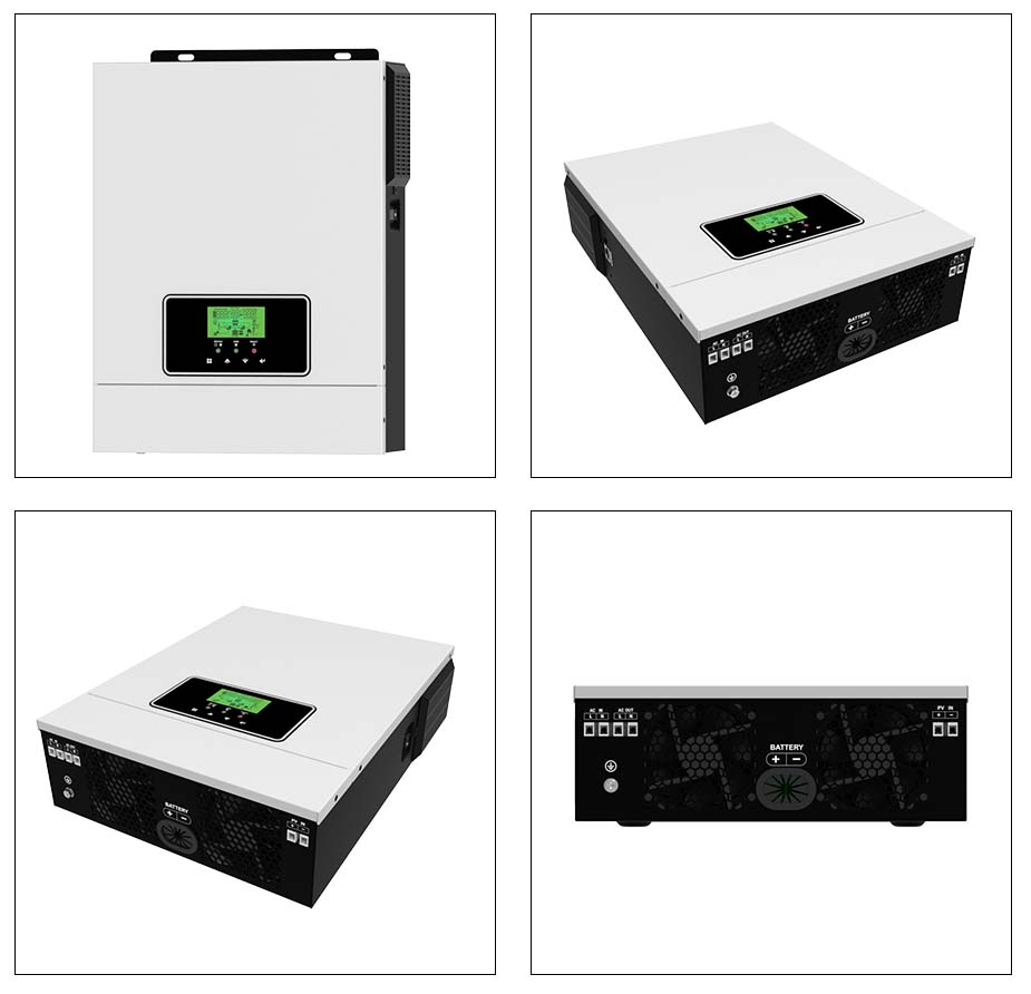
Equipment tolerance to harmonic distortion varies significantly based on internal circuitry and operational demands. Categorizing loads by their THD thresholds ensures safe and efficient power delivery. You must match the power quality to the specific requirements of the connected hardware to prevent operational failures.
Highly sensitive equipment requires a THD of less than 3%. This tier includes critical medical devices like CPAP machines and oxygen concentrators, advanced IT infrastructure, telecommunications gear, and high-end audio-visual systems. These devices require near-perfect waveforms and minimal frequency variation. Even minor distortions can cause data corruption, sensor inaccuracies, or complete operational shutdown. A dedicated sensitive appliance solar inverter is mandatory to maintain this strict power quality.
In a medical setting, for instance, a ventilator relies on precise timing circuits synchronized to the AC frequency. If harmonic distortion alters the zero-crossing point of the AC waveform, the timing circuit drifts, potentially causing the machine to trigger alarms or shut down. Similarly, high-end audio amplifiers will reproduce harmonic noise as an audible hum or buzz through the speakers, ruining the audio experience.
A THD of less than 5% serves as the industry standard for acceptable power quality, aligning closely with utility grid standards. Most standard refrigerators, microwaves, and lighting operate safely within this margin. The equipment will function normally provided voltage fluctuations remain within nominal tolerances during startup and continuous operation.
Modern appliances often contain internal switch-mode power supplies (SMPS) that convert the incoming AC back to DC for internal components. These SMPS units can handle minor waveform imperfections up to 5% THD without overheating. However, pushing beyond this limit stresses the input capacitors and rectifiers within the appliance, shortening its lifespan.
Operating above 5% THD introduces cascading risks to all connected hardware. High distortion levels frequently void warranties on sensitive equipment. For mechanical systems, it causes severe motor insulation degradation and drastically increases the probability of catastrophic hardware failure. Powering modern electronics in this danger zone is highly discouraged.
When THD exceeds 5%, induction motors experience a phenomenon called reverse torque. The harmonic frequencies create magnetic fields that oppose the primary rotation of the motor. The motor must work harder to overcome this internal resistance, drawing more current and generating excessive heat. Over time, this heat breaks down the winding insulation, leading to a dead short and complete motor failure.
The method an inverter uses to construct its AC output directly dictates the resulting harmonic distortion. Understanding the technical differences prevents critical system design errors. You must choose the right technology based on the loads you intend to power.
Modified sine wave inverters produce a blocky, stepped waveform. Instead of a smooth curve, the voltage snaps abruptly between high, zero, and low states. This crude approach inherently produces high THD, often ranging from 20% to 40%. The stepped waveform is accompanied by severe voltage variations. This makes modified sine wave technology entirely unsuitable for modern electronics or inductive loads.
The sharp transitions in a modified sine wave create high-frequency transients. These transients act like tiny hammer blows to the delicate internal components of electronics. Devices with thyristors or triacs, such as light dimmers or variable speed motor controls, rely on the smooth zero-crossing of a true sine wave to function. On a modified sine wave, these controls behave erratically or fail completely.
A true pure sine wave inverter utilizes advanced Pulse Width Modulation (PWM) and heavy LC (inductor-capacitor) filtering to smooth the waveform. This technology precisely controls the switching intervals, creating a fluid electrical curve. There is a direct correlation between this advanced filtering technology and achieving sub-3% THD. It ensures stable voltage and frequency output, replicating or exceeding the quality of standard grid power.
The PWM controller inside the inverter constantly monitors the output waveform and adjusts the switching duty cycle thousands of times per second to maintain the perfect sine shape. The heavy LC filters then strip away the high-frequency switching noise, leaving only the clean 50Hz or 60Hz fundamental frequency. This active regulation allows the inverter to adapt to changing load conditions instantly.
Inductive loads present unique challenges for off-grid power systems. Motors require clean power to generate efficient rotational force without overheating. You must account for the specific electrical characteristics of motors when selecting an inverter.
Harmonic frequencies create reverse torque in induction motors. These unwanted frequencies physically fight the fundamental frequency, pushing against the intended direction of motor rotation. This conflict results in severe overheating, increased power consumption, and a drastically reduced lifespan for HVAC compressors, well pumps, and heavy power tools.
Consider a 2-horsepower well pump operating on a high-THD power source. The 5th harmonic (300Hz on a 60Hz system) produces a negative sequence magnetic field. This field tries to spin the motor backwards. The motor draws additional current from the inverter to overcome this opposing force, causing the motor casing temperature to spike. This continuous thermal stress degrades the stator windings rapidly.
The sudden draw of inductive motor startups causes severe voltage sags and momentary frequency variations. A high-quality motor load power inverter must feature active voltage and frequency regulation loops. These control mechanisms prevent the waveform from collapsing or distorting during high-current inrush periods, maintaining stability when the motor demands peak power.
When a compressor kicks on, it can pull Locked Rotor Amps (LRA), which is often five to six times its normal running current. If the inverter cannot supply this massive current instantly, the output voltage drops. This voltage sag can cause other connected devices, like computers or televisions, to reboot or shut down. Active regulation loops detect this voltage drop in milliseconds and boost the inverter output to compensate.
Inductive loads demand massive inrush currents, often three to five times their running wattage. The inverter must handle this surge capacity while maintaining a clean, undistorted waveform. If the inverter's power factor correction is inadequate, the resulting voltage drop will stall the motor and potentially damage the inverter's internal components.
Power factor represents the phase alignment between voltage and current. Inductive loads cause the current to lag behind the voltage, resulting in a low power factor. The inverter must supply reactive power to support this lagging current. A robust inverter designed for motor loads includes heavy-duty transformers and oversized capacitors to handle this reactive power demand without distorting the primary sine wave.
Procuring the right inverter requires looking past marketing claims and analyzing specific technical parameters. Proper evaluation ensures long-term system reliability. You need to verify the data provided by manufacturers against real-world operating conditions.
Always look for explicit THD ratings measured at full load, not just at idle. An inverter may show 2% THD at 10% capacity but spike to 8% under maximum load. Reference established testing standards like IEEE 519 or UL 1741. These certifications serve as benchmarks for trustworthy power quality claims and verify the manufacturer's internal testing data.
When reviewing spec sheets, check if the THD is listed as a maximum value across the entire operating temperature range. Some inverters perform well at 25°C but suffer severe waveform degradation when operating in a hot utility room at 45°C. Third-party testing reports provide the most reliable confirmation of these specifications.
Choose an inverter with tight voltage regulation, typically ±1% to ±3%. Precise frequency stability, generally ±0.05 Hz to ±0.1 Hz, is equally important. These tight regulation windows safeguard microprocessors against drift and prevent timing errors in sensitive digital clocks and communication equipment.
Poor voltage regulation leads to flickering lights and erratic appliance behavior. If the frequency drifts beyond ±0.5 Hz, grid-tied equipment or synchronous motors will fail to operate correctly. High-end inverters use digital signal processors (DSPs) to monitor and adjust the output thousands of times per second, ensuring the voltage and frequency remain locked within these tight tolerances.
Size the inverter to ensure it remains in its optimal efficiency and lowest-THD operating window. This sweet spot is typically between 50% and 80% of its continuous capacity. Relying on peak surge ratings for continuous operation will elevate THD levels and rapidly degrade the inverter's internal components.
If you have a continuous load of 3000 watts, do not buy a 3000-watt inverter. Operating an inverter at 100% capacity continuously pushes the thermal limits of the internal components, increasing harmonic distortion and reducing lifespan. Instead, select a 4000-watt or 5000-watt unit to keep the continuous load within that 50-80% optimal range.
Internal heat severely impacts an inverter's ability to filter harmonics. As temperatures rise, component efficiency drops, allowing more distortion into the output waveform. High-quality capacitors and robust, oversized heat sinks are strong indicators of sustained low-THD performance under continuous, heavy loads.
Inspect the physical build of the inverter. Units with large, extruded aluminum heat sinks and variable-speed cooling fans manage thermal loads better than those relying solely on passive cooling or small, high-RPM fans. The quality of the internal electrolytic capacitors also dictates longevity; look for inverters specifying 105°C rated capacitors rather than standard 85°C components.
| THD Level | Power Quality | Suitable Load Types | Inverter Technology Required |
|---|---|---|---|
| < 3% | Excellent (Grid-equivalent or better) | Medical devices, IT servers, AV equipment, telecommunications | High-tier Pure Sine Wave with active LC filtering |
| 3% - 5% | Good (Standard utility quality) | Refrigerators, standard HVAC, lighting, general household appliances | Standard Pure Sine Wave |
| > 5% (Often 20-40%) | Poor (High distortion, stepped waveform) | Resistive heaters, basic incandescent lighting (Not recommended for electronics) | Modified Sine Wave |
Even with the right specifications, improper implementation or deceptive product marketing can compromise power quality. Proactive mitigation is necessary to protect your load. You must address system-level design flaws to maintain a clean power output.
The market contains cheap, white-labeled inverters that claim pure sine status but lack the internal filtering to maintain <5% THD under heavy loads. Read spec sheets critically. Look for THD and frequency stability ratings that span the entire operating temperature range and power spectrum. If the data sheet only provides idle specifications, disqualify the unit.
Some manufacturers use terms like "quasi-sine" or "pure sine equivalent" to mask modified sine wave technology. Always demand explicit THD percentages. If a manufacturer refuses to provide a detailed technical manual or third-party testing certificates, assume the product cannot meet strict power quality standards.
External factors frequently introduce harmonics and voltage variations. Poor grounding, undersized DC wiring, or interference from other non-linear loads on the same AC circuit will degrade power quality regardless of the inverter's capabilities. Ensure proper wire sizing to minimize voltage drop and isolate highly sensitive loads on dedicated circuits away from heavy inductive motors.
When installing the system, keep DC cable runs as short as possible and use appropriately sized wire to prevent voltage drop between the battery bank and the inverter. A significant DC voltage drop starves the inverter of power during surge events, causing the AC output voltage to collapse. Additionally, install proper grounding rods and bond the neutral and ground at the main panel to provide a clear path for fault currents and reduce electrical noise.
A: An acceptable THD is strictly <3% for sensitive electronics and medical devices, and <5% for general household use. High-quality pure sine wave inverters often operate below 2% THD, providing power that is cleaner than standard utility grids.
A: Yes. The high THD (often 20-40%) and rapid, stepped voltage variations inherent in modified sine wave inverters cause severe overheating and premature failure in microprocessors, digital clocks, and induction motors.
A: Harmonics create reverse torque in induction motors, fighting the fundamental frequency. This causes excess heat generation, severe efficiency losses, and voltage sags. Low harmonic distortion eliminates this reverse torque, ensuring smooth, cool operation.
A: High loads and rapid switching anomalies cause voltage sags and frequency drifts alongside harmonic distortion. This creates compound electrical stress on appliances. A high-quality sensitive appliance solar inverter actively regulates all three elements simultaneously to protect hardware.
A: You can measure THD accurately using a professional power quality analyzer or a digital oscilloscope. However, the best preventative step is verifying the manufacturer's IEEE 519 or UL 1741 testing certifications prior to installation.
A: Advanced internal filtering components require a small amount of operational power, slightly reducing overall conversion efficiency compared to crude modified sine wave units. However, this minor power consumption is necessary to prevent the destruction of expensive connected equipment.